+86-13532971605

For ADAS and automotive electronics, rapid temperature cycling is generally better for finding cumulative thermal-fatigue and functional failures, while thermal shock is more aggressive at exposing weaknesses caused by sudden temperature gradients—such as cracking, delamination, package damage, and seal problems.
The two methods are complementary rather than interchangeable. The correct choice depends on the expected vehicle environment, component construction, temperature transition rate, and the failure mechanism engineers need to accelerate.
ADAS modules combine materials with very different coefficients of thermal expansion (CTE): silicon dies, solder alloys, copper, PCB laminates, ceramics, aluminum housings, polymers, adhesives, and optical components.
Every rapid temperature transition causes these materials to expand or contract at different rates. Repeated stress can eventually produce:
BGA and solder-joint fatigue
PCB via and trace cracking
Connector contact instability
Package or underfill delamination
Adhesive and seal degradation
Camera alignment or calibration drift
Intermittent electrical faults
This is especially relevant for radar modules, camera ECUs, domain controllers, LiDAR electronics, power electronics, and sensors mounted near the windshield, bumper, roof, engine compartment, or other thermally exposed locations.
ISO 16750-4:2023 covers climatic stresses for electrical and electronic equipment based on vehicle mounting location, reinforcing the importance of matching environmental testing to the actual application.
Both tests alternate between high and low temperatures, but the transition severity is different.
Rapid temperature cycling normally changes chamber temperature at a controlled ramp rate. Thermal shock creates a much faster transition, commonly by moving the specimen between preconditioned hot and cold zones or switching conditioned airflow.
IEC 60068-2-14 distinguishes temperature-change methods and identifies temperature extremes, exposure time, transition conditions, cycle count, and specimen thermal response as important test parameters.
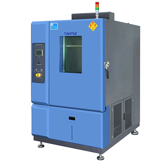
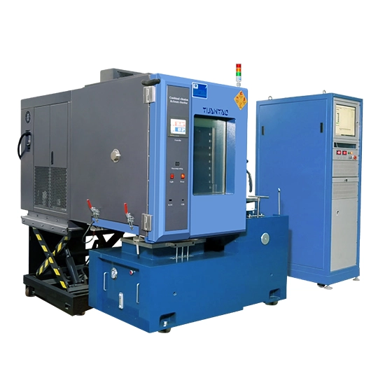
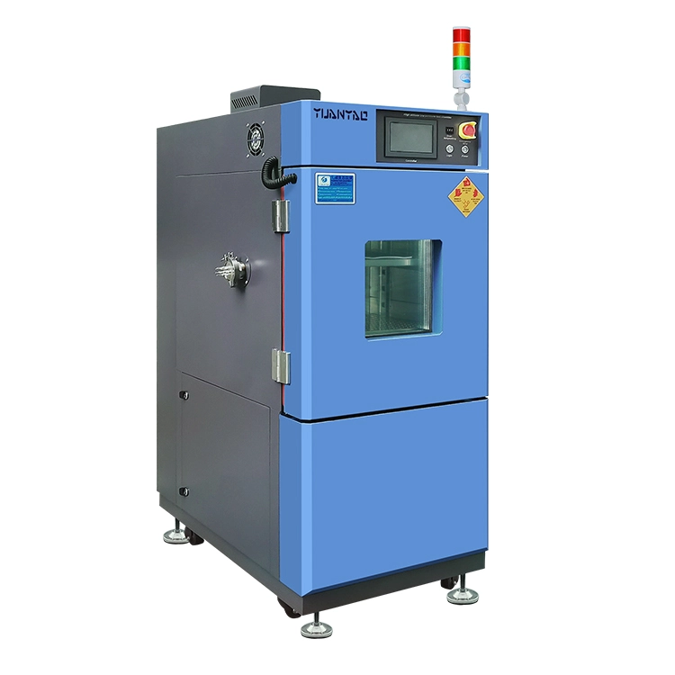
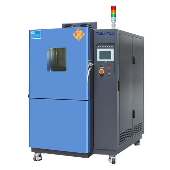
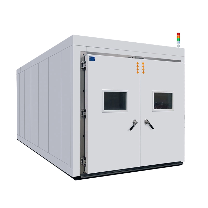
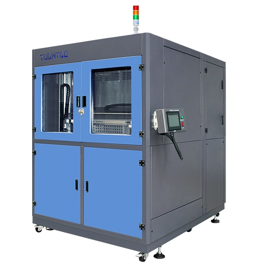
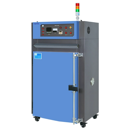
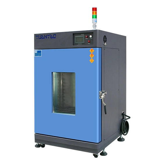
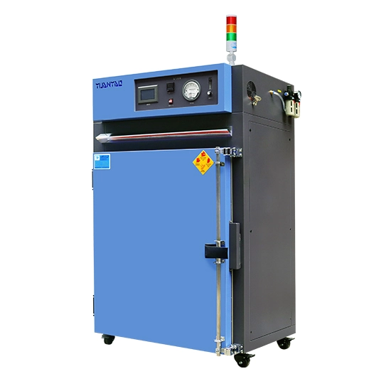
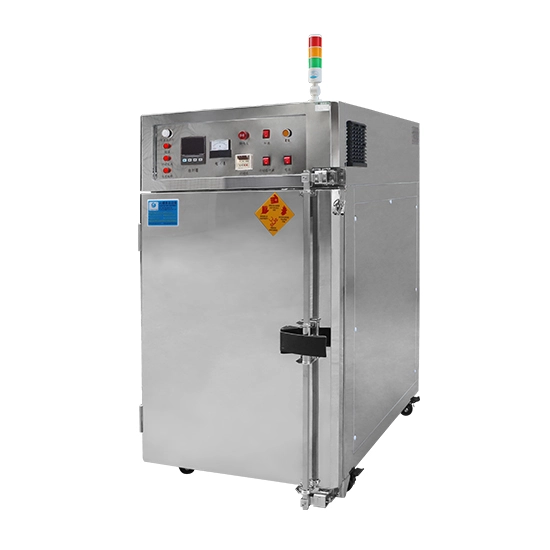
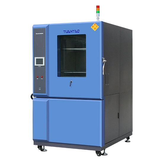
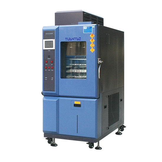
A rapid rate temperature chamber is particularly useful when engineers want to accelerate repetitive expansion-and-contraction fatigue while maintaining controlled temperature ramps.
It can help reveal:
Solder-joint fatigue. Repeated CTE mismatch places strain on BGA, QFN, LGA, and other solder connections.
PCB fatigue. Copper vias, plated through-holes, and laminate interfaces may develop cracks after repeated cycling.
Intermittent electrical faults. Connections can open temporarily at particular temperatures and recover afterward, making powered monitoring valuable.
ADAS performance drift. Cameras, radar electronics, processors, oscillators, and sensors can be monitored during temperature changes to detect calibration, communication, or signal-processing instability.
Long-term assembly weaknesses. Controlled cycling is well suited to accumulating hundreds or thousands of temperature transitions to study fatigue rather than only immediate fracture.
AEC automotive qualification specifications commonly reference temperature cycling using JEDEC JESD22-A104, illustrating the importance of repeated thermal stress in automotive component reliability.
Yuanyao rapid rate chambers provide programmable temperature-change rates including 3°C/min, 5°C/min, 8°C/min, 10°C/min, 15°C/min, and 20°C/min configurations, allowing test conditions to be selected according to the validation objective.
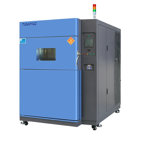
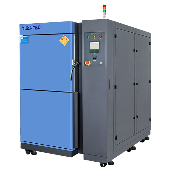
Thermal shock applies a more abrupt temperature transition and therefore creates larger short-term temperature gradients across the test specimen.
It is particularly effective for identifying:
Package and substrate cracking
Interface delamination
Ceramic or brittle-material fracture
Weak solder or intermetallic interfaces
Seal and adhesive failures
Rapid CTE-mismatch damage
Research involving an automotive ADAS assembly, for example, found progressive cracking in BGA solder-joint structures during repeated −40°C to +95°C thermal shock exposure.
For the same temperature extremes, thermal shock can create more severe instantaneous thermal stress because different parts of the assembly may heat or cool at different rates.
That does not automatically make it the better test. A thermal shock profile may over-stress a design if such transitions never occur in actual vehicle use. Controlled cycling may provide more meaningful results when the objective is long-term fatigue or powered functional validation.
| Validation objective | Preferred approach |
|---|---|
| Long-term solder fatigue | Rapid temperature cycling |
| PCB/via fatigue | Rapid temperature cycling |
| Powered ECU or ADAS functional monitoring | Rapid temperature cycling |
| Sudden package cracking | Thermal shock |
| Delamination and interface weakness | Thermal shock |
| Seal response to abrupt temperature change | Thermal shock |
| Realistic repeated vehicle temperature changes | Rapid temperature cycling |
| Worst-case rapid transition durability | Thermal shock |
For ADAS cameras and radar modules, engineers should also consider the actual specimen temperature, not only chamber air temperature. A large aluminum enclosure may respond much more slowly than a small semiconductor package.
When selecting rapid tech equipment for an automotive reliability laboratory, important specifications therefore include ramp rate under load, chamber uniformity, recovery performance, usable test volume, electrical feedthroughs, data logging, and the ability to monitor powered devices throughout the cycle.
The test profile should ultimately follow the applicable OEM specification, component qualification requirement, IEC method, ISO 16750 requirement, or validated field-use condition rather than using the chamber's maximum rate simply because it is available.
Rapid temperature cycling and thermal shock answer different reliability questions.
Use a rapid rate temperature chamber when the main objective is to accelerate repetitive thermal fatigue, detect intermittent electrical failures, and evaluate ADAS electronics during controlled temperature transitions. Choose thermal shock when the goal is to expose weaknesses that respond specifically to abrupt temperature gradients, including cracking, delamination, and interface failure.
For critical automotive electronics, using both methods at different stages of development can provide a more complete picture of product reliability.
Typical failures include solder fatigue, BGA cracking, PCB via damage, connector instability, delamination, and intermittent electrical faults caused by repeated expansion and contraction.
Yes, when the test method and safety conditions allow it. Powered testing is especially useful for detecting temporary communication errors, sensor drift, processor resets, and electrical interruptions that may not remain visible after the test.
There is no universal rate for every automotive product. The required rate should come from the applicable standard, OEM specification, mission profile, or reliability objective. IEC 60068-2-14 specifically treats temperature-change rate and specimen thermal response as important test parameters.
No. Thermal shock emphasizes abrupt thermal stress, while controlled cycling is particularly useful for accumulated fatigue and operational testing. For ADAS modules with complex packages, PCBs, connectors, optics, and housings, the two tests often reveal different weaknesses.

 English