+86-13532971605

Testing a complete telecom cabinet or network rack can reveal failures that component-level qualification never sees. Once servers, switches, power supplies, fans, cables, connectors, and control systems operate together, heat distribution, airflow restriction, humidity, and electrical loading become system-level reliability issues.
A properly configured walk in chamber allows engineers to test the fully assembled, powered system under controlled temperature and humidity conditions while monitoring the parameters that matter during real operation.
Individual boards, power supplies, and communication modules may all pass environmental testing and still fail after integration into a rack.
The reason is interaction between components. A populated cabinet creates its own thermal environment. High-power equipment heats neighboring devices, cable bundles restrict airflow, filters increase fan resistance, and hot exhaust air can recirculate toward equipment inlets.
Common full-system problems include:
Hot spots at the top or rear of the rack
Inadequate airflow around densely installed equipment
Power-supply derating at high temperature
Fan speed or fan-control abnormalities
Connector and cable failures during temperature changes
Unexpected thermal shutdowns
Network instability under combined thermal and electrical load
Condensation or moisture-related insulation problems
For telecom equipment, ETSI EN 300 019-2-3 addresses environmental testing for equipment used in stationary, weather-protected locations and includes temperature, temperature change, humidity, and condensation-related conditions.
Because the complete rack determines the actual airflow path, internal heat load, cable configuration, power distribution, and control behavior.
Component qualification verifies individual parts. Full-rack testing verifies whether those qualified parts still work correctly when assembled into the final thermal system.
As chamber temperature rises, the temperature margin available for internally generated heat becomes smaller. Processors, optical modules, power conversion devices, batteries, and switching components may approach their operating limits.
The resulting problems are not always immediate hardware failures. Engineers may first see:
Processor throttling
Reduced power-supply efficiency
Increased fan speed and power consumption
Packet loss or communication errors
Optical performance drift
Automatic shutdown or restart
Shortened component life
The key measurement is therefore not simply the chamber setpoint. Inlet-air temperature, exhaust temperature, and temperatures at critical internal components should also be recorded.
High humidity can contribute to insulation degradation, corrosion, leakage current, and long-term deterioration of connectors and electronic assemblies. Temperature transitions can also create condensation if the test profile crosses critical dew-point conditions.
IEC 60068-2-78:2025 provides a current test method for evaluating equipment under high-humidity, constant-temperature conditions without condensation and applies to both small components and large heat-dissipating equipment.
For complete telecom cabinets, chamber humidity control must therefore remain stable even when the powered rack itself introduces substantial heat into the test space.
A useful rack-level test should reproduce the operating condition rather than placing an unpowered cabinet in a hot room.
Start by defining the expected installation environment: indoor equipment room, partially conditioned shelter, outdoor cabinet, edge data center, or other application.
Then establish the test profile around several variables:
Temperature range. Select limits from product specifications, customer requirements, applicable standards, and expected installation conditions.
Humidity range. Include steady high-humidity exposure or cyclic conditions where moisture is a realistic field risk.
Electrical load. Run equipment at representative and, where appropriate, worst-case traffic and power loads.
Airflow configuration. Keep doors, filters, fans, blanking panels, cables, and rack spacing consistent with the intended installation.
Stabilization time. A large rack has substantial thermal mass. Do not begin performance evaluation simply because chamber air has reached its setpoint.
Temperature transitions. Evaluate startup, shutdown, and operating behavior during changing conditions if these transitions are relevant to field use.
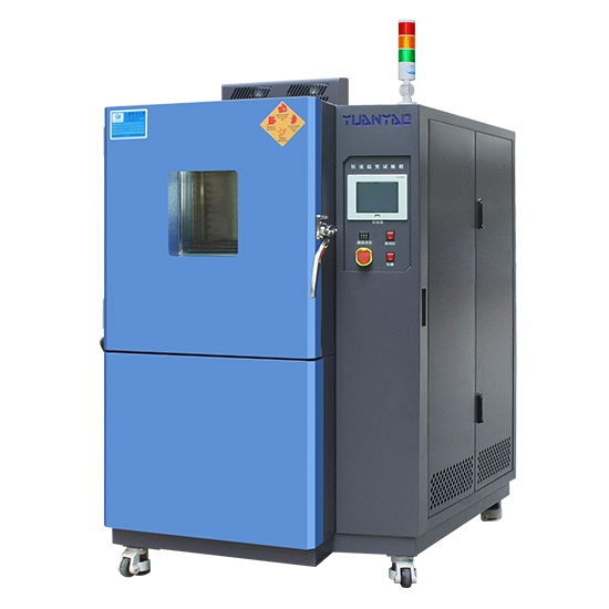
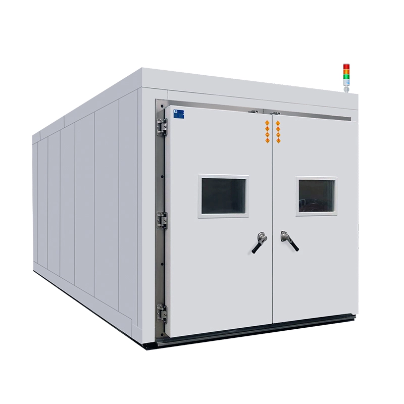
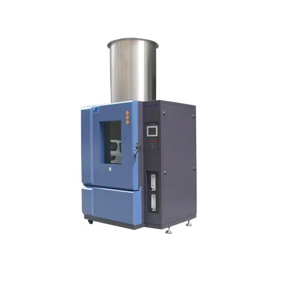
A large walk in chamber is particularly useful because the rack can remain assembled, powered, and instrumented throughout the test. Yuanyao's walk-in temperature and humidity chambers are designed for large products and can be customized in size according to test requirements.
A chamber temperature graph alone is not enough to determine whether a telecom system has passed.
For a powered network rack, useful measurements include:
| Parameter | What It Can Reveal |
|---|---|
| Rack inlet temperature | Whether equipment receives acceptable cooling air |
| Rack exhaust temperature | Overall heat rejection and recirculation |
| Component temperatures | Local overheating not visible from chamber sensors |
| Fan speed/current | Cooling-system response and degradation |
| Power consumption | Efficiency changes and abnormal loading |
| Voltage/current rails | Power instability under environmental stress |
| Packet loss/error rate | Network performance degradation |
| Optical signal performance | Temperature-related transceiver drift |
| Alarm and reset logs | Intermittent system failures |
| Relative humidity | Moisture exposure and condensation risk |
Sensor placement matters. For tall cabinets, measurements should normally be distributed across different rack heights and around known high-power equipment rather than concentrated at one point.
Yes, and powered testing is often essential when the objective is full-system reliability.
Electrical feedthroughs can connect the equipment to external power, monitoring systems, network traffic generators, and data-acquisition instruments. The chamber must, however, be sized and engineered for the heat dissipated by the equipment under test.
A rack releasing several kilowatts of heat can significantly affect chamber performance. Cooling capacity should therefore be calculated with the live test load included.
The walk in environmental chamber price depends on considerably more than internal dimensions.
Major cost factors include:
Chamber volume
Temperature range
Humidity range
Heating and cooling capacity
Heat load from powered equipment
Temperature change rate
Insulation and panel construction
Number of cable and electrical feedthroughs
Control and data-logging requirements
Safety protection
Custom doors, floors, ramps, and access ports
For telecom racks, buying an oversized chamber with insufficient refrigeration capacity can be just as problematic as choosing a chamber that is physically too small.
When comparing a walk in chamber manufacturer, provide the supplier with the rack dimensions, total weight, maximum electrical heat load, required temperature/humidity profile, cable requirements, and applicable test standard. This allows the refrigeration and air-circulation system to be engineered around the actual application instead of only the empty chamber volume.
Full-system environmental testing answers questions that component qualification cannot: whether cooling works after integration, whether hot spots develop inside the cabinet, whether the network remains stable at environmental limits, and whether humidity or temperature transitions cause intermittent failures.
For telecom cabinets and network racks, an effective walk in chamber should reproduce the required environmental conditions while handling the heat output of fully powered equipment. Selecting the chamber around actual rack load, airflow, instrumentation, and test standards produces much more useful reliability data—and reduces the risk of discovering integration problems after deployment.
The chamber should provide adequate clearance around the rack for airflow, sensors, cabling, and service access. Chamber size should be determined from the complete installation layout rather than rack dimensions alone.
Dwell time should allow the complete rack—not only chamber air—to reach the required thermal condition. Large cabinets can have significant thermal inertia, so internal temperature measurements are important when determining stabilization.
Yes, provided the chamber has sufficient space, airflow uniformity, refrigeration capacity, electrical capacity, and instrumentation. The combined heat load of all powered racks must be considered during chamber sizing.
Requirements depend on the equipment and installation environment. ETSI EN 300 019 series specifications are commonly relevant to telecommunications equipment, while IEC 60068 methods cover environmental stresses such as temperature changes and damp heat. The specific test profile should follow the applicable customer, industry, or product requirement.

 English